After going through the effort to swap out the JLD-404 meter and test the new one with 3 different shunts, I finally discovered the root cause of the current measurement inaccuracy. The meter comes with the default current input setting on a 5 Amps scale. The choices are 5 amps, 1 amp or 75 mV. While being diligent to input the correct shunt value at full scale, on both meters I had left the the current input on the default setting. All I had to do was change A-Sn = 75mV. That was it!!!
Now another mystery presented itself. The old meter would always retain the recorded amp-hours, but the new meter would reset to zero every time power was turned off to the meter. I asked for my old meter back and returned the loaner/replacement. It is now installed and all is well. The current is now within 1% of the actual. A very small fudge factor in the shunt setting and it is reading spot on.
Sunday 28 September 2014
Friday 5 September 2014
Meter Replacement
After reading that a batch of JLD-404 meters were reported to have incorrect internal resistors, I contacted ECPC about a replacement. They promptly sent a new meter which I promptly installed.


Unfortunately, I am having the exact same issue with the meter reading low on Amps. In the programming set points, I enter APuH = 150 amps (which is the value when reading 75mV across my 200Amp-100mV shunt).
Here is a picture showing that the meter is reading 1.7 amps while the Fluke is reading 2.2 amps (conversion = 1.1 mV times 2 = 2.2 amps)
I have to enter APuH = 185 amps to get readings which correspond to my Fluke multimeter and to my battery charger meter. Here the meters are in sync at 2 amps.
I have carefully:
1. Checked the wiring installation.
2. Validated the programming entries
3. Measured the mV with my Fluke multimeter directly across the shunt terminals and also using the same wires as the meter
4. Confirmed that there is no current flowing on the meter positive or common wires connected to the shunt
From a practical standpoint, the fudge factor is adjusting for the error, but I would like to solve this mystery.
Thursday 2 January 2014
Installation of a High Quality Shunt and Check of JLD404 Amp Reading Accuracy
The Amico 200 amp-75 shunt purchased off of Amazon.com is only rated as +/- 1% accuracy. I used this inexpensive Chinese steel shunt to verify the golf cart current draw runs below 60 amps with spikes to 140 to 180 amps. The JLD-404 mV range is 0-75 mV. With this information I ordered a high resolution brass shunt from Galco.com that is +/- 0.25% accurate. This FN series base-mount shunt manufactured by Crompton Industries in Mexico is a 200 amp - 100 mV shunt with resistance of 0.0005 ohms. There is no comparison between the quality of the two shunts. This heavy brass shunt is over 5 inches long and comes with a thick 6" inch long plastic base mount.
Here is a picture of the new shunt attached to the side of the plastic battery box using 2 short flat head screws. The large brass bolts are the attachment points for the negative battery lead wire (blue insulation) and the black negative wire to the controller. Some additional leads from accessories attach to the controller side of the shunt so that all of the current will be measured. Note that the large studs require 3/8" holes which required modification of my cable lead terminals. I carefully drilled out the large lugs using a c-clamp and a backer board. The smaller rings on the accessory cables were snipped and pried open to the required diameter.
The pair of small red and black lead wires in the middle of the shunt go to the JLD-404 meter.

Over the range of the JLD-404 meter, at maximum 75 mV the amp reading should be 150 amps. This value is typed into the meter in order that the current can be calculated and displayed. Unfortunately, I observed with both shunts that there is a difference between the mV measurements using my Fluke multimeter and the corresponding amp readings from the JLD-404.
Picture of the JLD-404 reading 2.0 amps (cart headlights on and ignition key on)

Here is a picture of the Fluke attached to the same leads wires with the same load. The 1.2 mV translates to 2.4 amps using the shunt resistance of 0.0005 ohms (just multiply the displayed mV value by 2X or divide the actual mV by the shunt resistance I=V/R).

Picture with the meter leads directly touching the contact points on the shunt produced the same reading 1.2 mV (2.4 amps)

The current flow was confirmed by using the amp meter function and flowing the current through the Fluke. I measured 2.35 amps.
I am not sure if the meter error is due to round off or low impedance of the JLD-404? I plan to test at higher current flows. If the difference exists at all ranges I may have to try installing a high value resistor in series with the meter leads. For now I might try using a different conversion factor.
Update: The meter was consistently under recording amps at both low and high current. I "calibrated" the meter by entering a higher maximum amp setting into the JLD-404. Instead of 150 amps, I found that 200 amps brings the displayed measurement in line with the Fluke. I still would like to find and address the root cause. In the Feb 24, 2012 EVTV episode at 80 minutes, Jack talks about installing a DC-DC converter to isolate the meter. http://evtv.projectooc.com/index.php?showid=124
Based on this video, I placed an order with Mouser Electronics for a Mean Well SPU03M-12 DC-DC 3-Watt Converter. This little encapsulated chip with 4 pins will accept 8 to 13 volts input and output 12 volts. Most importantly it provides 3,000 Volts of DC isolation. When it arrives, I will have to solder on 2 pair of lead wires and connect between the incoming power and the meter input. Hopefully this will solve the accuracy problem and protect the pack from additional current leakage.
Quick mileage test. Using the amp-hour function of the JLD-404 I drove the cart for 2 miles on surface streets which included both starts and stops. With myself as the only rider, the EZGO RXV with it's 4.4 hp AC-drive motor and regenerative braking got 1.8 amp hours per mile. Using 80% or 80 amp-hours of usable capacity for my 100 amp-hour cells, this translates into 44 miles on a charge. This is in line with my estimates during the pack design.
Installation of the EX-RAY Speedometer
A speedometer with mileage odometer is needed to determine the cart "mileage" measured in amp-hours / mile or watt-hours / mile. I ordered an EX-RAY speedometer from EVDrives.com. This speedometer also contains a battery pack voltage measurement, air and motor temperature, and clock.
Upon opening the box I discovered that I had not specified the RXV model. The machined aluminum mounting bracket was too small for my cart. I called Carl and arranged for an exchange. When the new speedometer arrived I set about installation.
The first challenge is removing the driver side front wheel. Should be easy enough but the bolts were frozen in place. A little WD-40 and 10 minute wait did the trick. I used the jack from my pick-up truck to lift the front end of the golf cart.

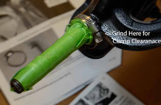
On the RXV model the clamp that holds the magnet sensor does not have enough clearance, it requires pulling the hub and doing some grinding on the cast webbing. Fortunately I had a 4" Makita hand held grinder. This did not take but a few minutes. The axle was covered with green Frog tape to keep the filings from getting into the bearings.
Next the magnet that rotates is mounted on the aluminum wheel hub. This requires drilling and counter sinking a bolt into the hub.

Here is the magnet and sensor in place with about 1/4" of separation.

The speedometer contains a small flat watch battery, but works best with external power (which also allows measurement of the pack voltage). This should be from switched 48 volt system, which required some testing to find.
With everything assembled I turned on the cart ignition switch and it worked first time! Final steps are to set the units, the clock time and input the wheel circumference in millimeters. I measured this directly by putting a thin line of paint on the wheel and rolling the cart until I could see 2 marks on the floor (used cardboard to keep the paint off the cement).
With the speedometer I confirmed that the cart top speed is 20.4 mph. This is a relief as the local sheriff is giving tickets for unlicensed vehicles that are caught driving over 20 mph on a surface street.
Upon opening the box I discovered that I had not specified the RXV model. The machined aluminum mounting bracket was too small for my cart. I called Carl and arranged for an exchange. When the new speedometer arrived I set about installation.
The first challenge is removing the driver side front wheel. Should be easy enough but the bolts were frozen in place. A little WD-40 and 10 minute wait did the trick. I used the jack from my pick-up truck to lift the front end of the golf cart.

On the RXV model the clamp that holds the magnet sensor does not have enough clearance, it requires pulling the hub and doing some grinding on the cast webbing. Fortunately I had a 4" Makita hand held grinder. This did not take but a few minutes. The axle was covered with green Frog tape to keep the filings from getting into the bearings.

Next the magnet that rotates is mounted on the aluminum wheel hub. This requires drilling and counter sinking a bolt into the hub.

Here is the magnet and sensor in place with about 1/4" of separation.

The speedometer contains a small flat watch battery, but works best with external power (which also allows measurement of the pack voltage). This should be from switched 48 volt system, which required some testing to find.
With everything assembled I turned on the cart ignition switch and it worked first time! Final steps are to set the units, the clock time and input the wheel circumference in millimeters. I measured this directly by putting a thin line of paint on the wheel and rolling the cart until I could see 2 marks on the floor (used cardboard to keep the paint off the cement).
With the speedometer I confirmed that the cart top speed is 20.4 mph. This is a relief as the local sheriff is giving tickets for unlicensed vehicles that are caught driving over 20 mph on a surface street.
Installation of JLD-404 meter
The two main rules with Lithium batteries are to never over charge or over discharge. The charger shuts down automatically on the top end at a safe level (assuming the cells are top balanced). On the discharge, it is important to know the state-of-charge of the cells. Due to the flat discharge curve, voltage is not a good approximation of charge as it is with lead-acid batteries.
The best way is to count amp-hours (or watt-hours). The emerging standard in the EV community is the JLD-404 meter. Here is the meter connected to lead wires, but not mounted. The EX-RAY speedometer is also shown mounted on the steering column, but not hooked up.

The meter requires 12 to 30 Volts DC, preferably un-switched so that the meter retains the settings. All low power out of the EZGO DC-DC converter were wired for switched power, so I had to install a new pin in the unused un-switched position. This wire and a ground wire fed the meter.
A separate pair of lead wires were connected to the 200 amp shunt for measuring mV readings from 0 to 75 mV which are converted into amps based on the resistance of the shunt.
One addition wire was connected to the positive lead of the pack to allow measurement of the pack voltage.
All of the wires between the dash and the battery compartment had to go in the wiring channel beneath the floor mat. Note that all of these screws/bolts use the TORX style driver tool which required another trip to the hardware store.
Finally the meter was secured to the underside of the dash with a plastic strap and 2 screws. The battery switch was turned on. It came on for an instant then died. Even though the meter only draws 0.04 amps I suspected the 0.2 amp AGC glass fuse in the power lead wire. Sure enough the surge during power up blew the fuse and did the same with a second one. Another trip to the auto parts store for a 2 amp fuse. Power on and it came to life! The settings were input using the information from the on-line manual posted by EVTV; thank you Jack.
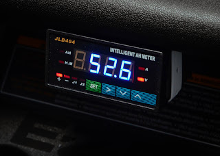
Here is the meter displaying amp-hours


Here the meter is displaying the pack voltage
A quick test drive confirmed that it seemed to be working as it was supposed to.
Next post, installation of the EX-RAY speedometer/odometer.
The best way is to count amp-hours (or watt-hours). The emerging standard in the EV community is the JLD-404 meter. Here is the meter connected to lead wires, but not mounted. The EX-RAY speedometer is also shown mounted on the steering column, but not hooked up.

The meter requires 12 to 30 Volts DC, preferably un-switched so that the meter retains the settings. All low power out of the EZGO DC-DC converter were wired for switched power, so I had to install a new pin in the unused un-switched position. This wire and a ground wire fed the meter.
A separate pair of lead wires were connected to the 200 amp shunt for measuring mV readings from 0 to 75 mV which are converted into amps based on the resistance of the shunt.
One addition wire was connected to the positive lead of the pack to allow measurement of the pack voltage.
All of the wires between the dash and the battery compartment had to go in the wiring channel beneath the floor mat. Note that all of these screws/bolts use the TORX style driver tool which required another trip to the hardware store.
Finally the meter was secured to the underside of the dash with a plastic strap and 2 screws. The battery switch was turned on. It came on for an instant then died. Even though the meter only draws 0.04 amps I suspected the 0.2 amp AGC glass fuse in the power lead wire. Sure enough the surge during power up blew the fuse and did the same with a second one. Another trip to the auto parts store for a 2 amp fuse. Power on and it came to life! The settings were input using the information from the on-line manual posted by EVTV; thank you Jack.
Here is the meter displaying amp-hours

By clicking the ">" button you cycle through AH, Time, Amps and Volts. Here it is displaying amps. I have found that it takes about 0.2 amps to keep the contactor closed when the cart ignition key is on.

Here the meter is displaying the pack voltage

A quick test drive confirmed that it seemed to be working as it was supposed to.
Next post, installation of the EX-RAY speedometer/odometer.
Subscribe to:
Posts (Atom)