Cell Capacity
Not every cell has exactly the same capacity as illustrated in the figure below. In this case cell “B” has only 95% of the rated name plate amp-hour capacity while cell "C" has 105%.
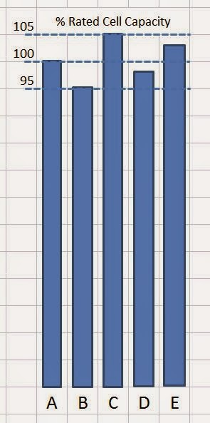
The combination of these two factors cause the useful amount of amp-hours in the entire pack to be limited by the lowest cell. In this example, cell "B" will be the first to discharge / charge.
Let's see why the lowest cell is the limitation and some alternatives to deal with it.
Top Balancing
Let’s say that you carefully charged each cell so that they were all completely full as determined by the cell voltage. A typical “cut off” charge voltage for LiFePO4 cells is 3.65 volts. With each cell at this voltage you have effectively balanced the pack at the top of the charge. See figure below (left).

The challenge is that it is difficult to know which cell is empty. The voltage of entire pack may look fine, but one cell can still be below the critical value. The only way to be sure is to have a system that measures the voltage of each cell, or at least small groups of cells.
Bottom Balancing
There is another approach. That is called bottom balancing which is performed by individually draining each of the cells to the same lower voltage level (figure below – left). Note that this illustration shows 2.50 volts, but bottom balancing is often done at a more conservative 2.70 volts. Now when you drive the cart you can tell from just looking at the total pack voltage when to pull over and call the tow truck as all of the cells reach empty at the same time.

How do you do that without a cell-level monitoring system?
Options include having individual chargers for each cell, under charging the pack and hope that none of the lower-capacity cells were damaged, or manually checking the voltage of each cell toward the end of the charge to find an optimal cut-off point.
Battery Management System
A third engineering alternative is to measure voltages on each and every cell during charge and discharge. Alarms can provide warnings and, in some designs, the controller can turn off the charger on the top end and-or shut down the system when the lowest capacity cell is empty. These systems are referred to as a BMS or Battery Management System. In addition to adding cost to a golf cart application, some of my personal concerns regarding a BMS are the complexity (reliability), uncertainty (what the BMS is doing to my cells), and amount of exposed circuitry (failure rate).
Many designs also attempt to move small amounts of current from higher capacity cells to lower capacity cells, especially during charging. The use of a BMS is frequently combined with top balancing.
Which is correct? You will find very strong opinions with heated arguments for each of these techniques. My view is that all with work just fine if you understand the approach and follow the procedures for that alternative.
My Design and Operating Choice
Which way am I going? This is a golf cart and I want a simple low cost system. Regardless of which approach you take, I am convinced that all lithium packs should have an amp-hour counter (or watt meter) to provide an indication on the state-of-charge. These devices actually take mV readings across an externally mounted shunt (calibrated resistor). I will be using the common JLD-404 meter, cost $75 and a 200 amp / 75mV shunt.
I would have gone with top-balancing combined with voltage measurement and alarm for four groups of 4 cells each. The rational was that any cell that dropped into the danger zone would be easily detected. This would only require 5 fused wires. While searching for parts I found some interesting options designed for the radio-controlled toy airplane / helicopter hobbiest.
Now the plan is to go with top-balancing combined with full cell-level monitoring and low voltage alarms. This will be provided by a pair of tiny Cell-Log 8M devices attached to the dash.
http://www.progressiverc.com/celllog-8m.html
The drawback is that design will require 17 fused wires and then unplugging of the Cell-Logs when not in use as they have a small parasitic current draw that is un-even from each cell. Thanks to Ken's MR2EV conversion blog for the tip and details. http://blog.mr2ev.com/should-you-install-a-battery-management-system-to-protect-those-expensive-lithium-batteries/
Since only 2 knowledgeable and responsible adults will be using the cart, a mistake-proof auto-shut down system was not thought to be needed. I can also forgo the cost and complexity of a full cell-level BMS.
My pack will be protected at the top end where charging occurs frequently, I should have an indication of the state-of-charge from the amp-hour meter to let me know when to start home. Should there be a surprise, an alarm will signal any problem toward the bottom. The appropriate decision on how to handle can be made at that point.
No comments:
Post a Comment
Please leave your feedback and share your thoughts and experiences, but please be factual and keep the tone friendly. Personal attacks and political references will be deleted.